ABOUT THE PRODUCT
Articles 23-03-2021, 16:03 5 635 print
The photo crack meter consists of:
➔ set of pair of photogrammetric markers - special pictures with unique numbers, printed on the plate, which are fixed along both sides of a crack or an expansion joint (Fig. 1);
➔ any modern camera with the optical zoom required for certain shooting conditions;
➔ PhotoMicrometer software.
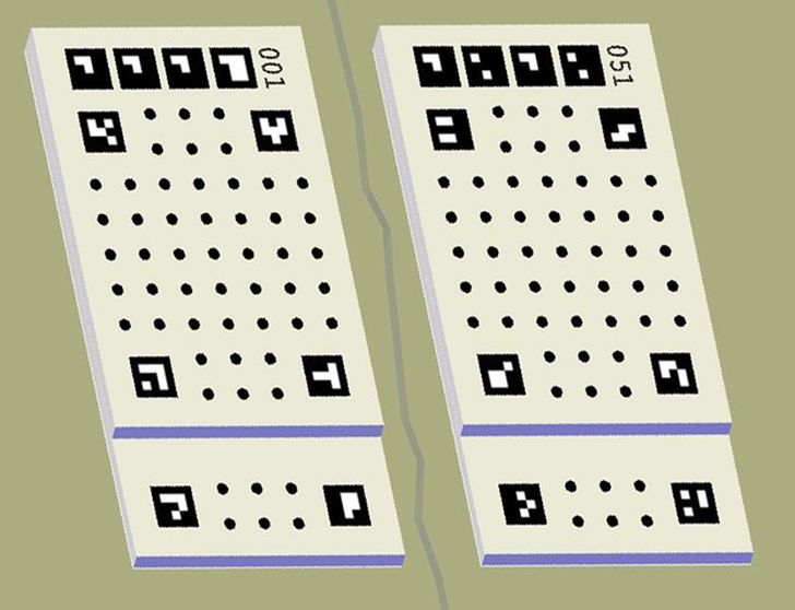
Fig. 1. The photo crack meter – two Photogrammetric markers attached on opposite sides of the crack.
The principle of monitoring is based on taking a picture of the markers by camera and using PhotoMicrometer software for photogrammetric processing of images in order to obtain a relative position of the centers of two markers in the three dimensional rectangular coordinate system (R point position in the OXYZ coordinate system, Fig. 2). The origin of the coordinate system (point O) is always positioned on the lower-numbered marker, the positive Z-axis points up, the positive Х-axis points to the right and the positive Y-axis points into the plate.
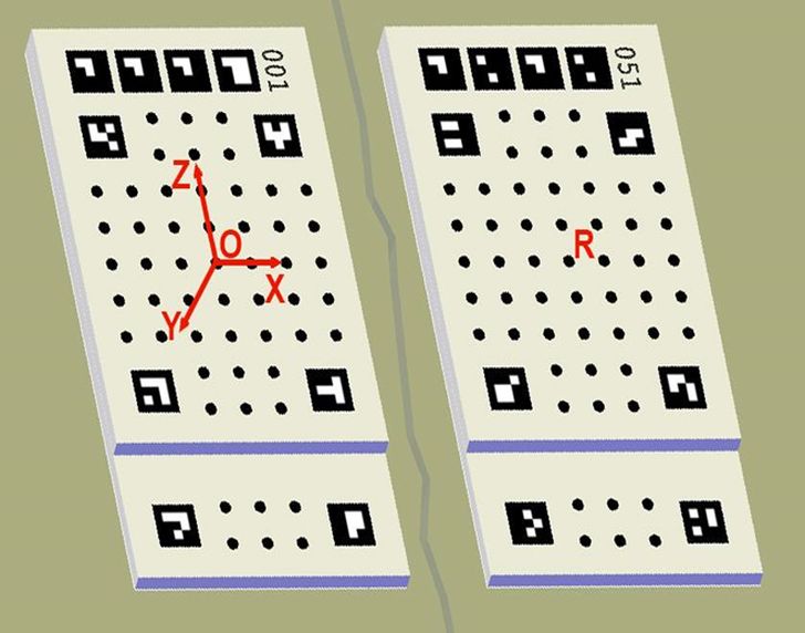
Fig. 2. Coordinate system.
Comparing the results of photogrammetric processing of images taken at different times (indifferent observation cycles), we determine the relative displacement of the markers.
This approach allows to monitor under different conditions (indoors, at the elevation of building, on bridges and at the industrial installations) and at different shooting distances (from 0.1m to 40m) between the camera and the object observed. Image processing in PhotoMicrometer is based on methods of photogrammetry, stereophotogrammetry, and also is based on high-precision measuring of marks. This allows monitoring with an accuracy of 0.1 mm to 0.005 mm, depending on the types of markers used. The deformations that the method allows you to measure with guaranteed accuracy can reach up to 5 cm on each coordinate axis.
The photo crack meter is one of the three main components of the complex. It performs the following main functions:
- fixing the monitoring location;
- setting the scale and coordinate system for monitoring;
- contains the source data for photogrammetric calibration of images.
Currently, three types of markers are produced, designed for different indicators of measurements accuracy.
| № | Marker Type | Accuracy |
| 1 | М-0.1 | 0.1 mm |
| 2 | М-0.02 | 0.02 mm |
| 3 | М-0.005 | 0.005 mm |
The value of the root-mean-square error in determining the mutual position of the centers of two markers was taken as a measure of accuracy, obtained from processing a pair of images taken at a distance of 2 meters and with an intersection angle of 90 °.
Markers of different types look the same. The difference is in the accuracy and, accordingly, the complexity of the program for their calibration, the results of which are recorded in the calibration file and supplied with the markers.
Currently, we have mastered the production of markers from the following materials:
• PVC plastic (letter P)
• aluminum (letter A)
• fiberglass (letter T)
Information about the material of production is indicated in the type of beacon to the right of the accuracy indicator, for example, M-0.1 P, M-0.02 A or M-0.005 T – the first is made of PVC, the second is made of aluminum and the third is made of fiberglass.
All these materials have sufficient mechanical strength and stability, but have a different coefficient of thermal expansion (in aluminum, it is about 3 times higher than fiberglass, and in PVC-three times higher than aluminum). And, although, the software takes into account the corrections for the temperature – it cannot always be known with sufficient accuracy. Therefore, when performing high-precision observations in conditions of a strong temperature difference, it is desirable to use markers made of a more stable material in this respect.
Markers are attached on both sides of the crack, either with glue or with screws.
In the first case, any glue can be used that will provide a reliable fixation during the entire monitoring time: epoxy, "liquid welding", "two-component glue-plasticine", etc. The use of mounting tape can be quite reliable and convenient in some cases.
If the attachment with glue, for some reason, does not suit, - markers can be fixed on the screws, using a special type of washer, which we have specially developed for attaching photo markers.
Also some dealers offer their own mounting options based on their experience in monitoring.
The system is organized in such a way that all images undergo photogrammetric calibration during processing. This makes it possible to use any modern photo or video camera for monitoring (from a phone to expensive mirror equipment) and get high-quality results.
Nevertheless, the camera is one of the three main elements of the technology, and the accuracy of the results directly depends on the quality of the images and the correct shooting.
The most important requirement for the camera is the ability to provide sufficient detail of the image of the marker when shooting from the required distance. This depends primarily on the camera's focal length. The relationship between the shooting distance and the required focal length of the camera is presented in the table:
| Shooting distance (m) | 0.2 | 1 | 5 | 10 | 20 | 30 | 40 |
| Equivalent focal length of the camera (mm) | 14–55 | 40-200 | ≥200 | ≥400 | ≥800 | ≥1200 | ≥1600 |
The equivalent focal length of the camera is given in terms of the 36x24 mm frame format for matrices with a resolution of 15 - 20 megapixels.
It is convenient to use cameras with lenses that have a variable focal length (Zoom lenses). So, using, for example, a TV-camera and a tripod, you can take pictures of markers located on the 10th floor of a building in the process of monitoring from the ground.
Another way to get a detailed image of a hard-to-reach marker is to use a quadrocopter.
For photographing at close range any camera is suitable.
2 methods of photographing can be used for monitoring – photogrammetric (shooting and processing single images, Fig.3) and stereophotogrammetric (shooting and processing two or more images, Fig. 4).
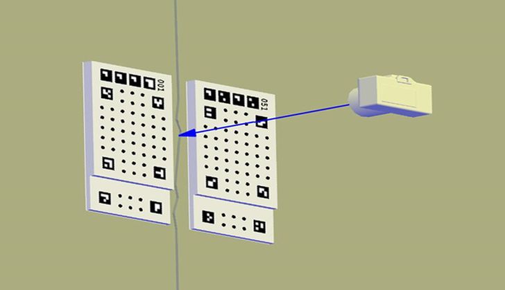
Fig. 3 Shooting and processing single images
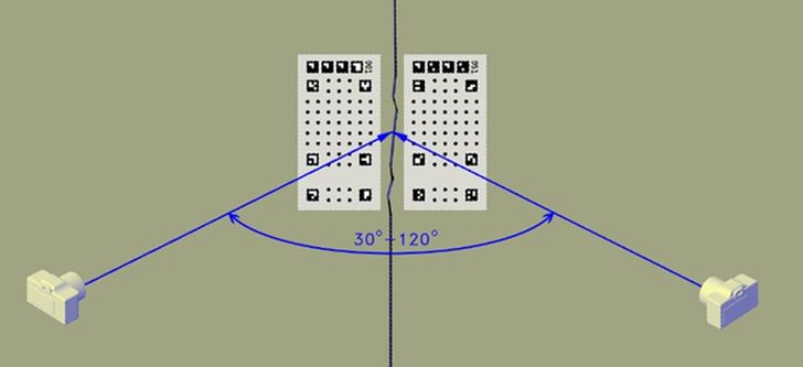
Fig. 4 Shooting and processing two or more images
Stereophotogrammetric method is the main method of photographing. It provides a stable high accuracy of 3D measurements over the entire range of distances from 0.1 to 40 meters.
The photogrammetric method provides high accuracy of 3D measurements at photographing distances up to 0.3 m. At large shooting distances (up to 40 meters), single-image measurements can be used to monitor 2D movements in the wall plane. At the same time the pair of markers must be strictly on the same plane.
PhotoMicrometer is a photogrammetric program specially developed to work as part of a monitoring complex and implements a full processing cycle - from measuring images to forming a technical report. Due to the high level of automation of all processes, it is not necessary to have a deep knowledge of photogrammetry to master working with the complex.
The PhotoMicrometer system is based on theoretically rigorous photogrammetry methods: high-precision markers measurement algorithm, forward and reverse photogrammetric serifs with simultaneous calibration of images and equalization of the determined parameters using the least squares method. Thanks to the theoretically rigorous and technically advanced algorithms of the solution, almost any digital camera can be used to work with the system. At the same time, there is no need to pre-calibrate it.
PhotoMicrometer can be used for processing of both single images (photogrammetric method) and multiple images (stereophotogrammetric method). The program supports processing of various types photo markers (accuracy classes), rebuilding the interface taking into account this parameter.
For each observation cycle, a project is created in the program. The images (image) of this cycle are uploaded to the project. When loading, the program automatically detects the number of the photo markers and applies its calibration data to the project. If the monitoring is performed under different temperature conditions, the temperature must be entered into the project during the survey to account for the linear expansion coefficient. All data, as well as the results of measurements and calculations, are recorded in a file with the *.pmm extension.
The processing begins with the mark measurements on the marker photographs. This process is automatical, although, just in case, a semi-automatic mode is also provided. Then, the measurement results are adjusted parametrically. Based on the results of the adjustment, the position of the center of the right marker in the coordinate system of the left marker is found (Fig.2), and the accuracy is evaluated based on the results of the adjustment.
If all the project files of the corresponding observation cycles are in the same folder, the monitoring results can be visualized by plotting the movement along the three coordinate axes. The processing ends with the formation of a report, where, in addition to graphs, the results of the accuracy assessment and some other parameters are entered. The report can be saved in a *.xml file, and the calculation results can also be saved in text format.
SPECIFICATION
of the supplied equipment and software those are parts of the photogrammetric complex Photo crack meter, developed for monitoring cracks and expansion joints in buildings and structures
| EQUIPMENT | ||||
| № | Name of the supplied hardware or software | Accuracy of determining deformations or displacements on each coordinate axis | Complete set | Price (euro) |
| 1 | Set of photogrammetric marks M-0.1 (2 pcs.) for installation on both sides of the crack | 0.1 mm (MSE) | Completed with calibration file | 20 |
| 2 | Set of photogrammetric marks M-0.02 (2 pcs.) for installation on both sides of the crack | 0.02 mm (MSE) | Completed with calibration file | 35 |
| 3 | Set of photogrammetric marks M-0.005 (2 pcs.) for installation on both sides of the crack | 0.005 mm (MSE) | Completed with calibration file | 45 |
| SOFTWARE | ||
| The name of the software, its purpose, and the complete set | License period | Price (euro) |
| The name of the software – PhotoMicrometer. The program allows to perform automated processing of images of photogrammetric marks fixed on both sides of the crack and evaluate their relative positions, as well as displacements and deformations in a three-dimensional coordinate system. | 1 month | 45 |
| 2 month | 65 | |
| 6 month | 125 | |
| 1 year | 190 | |
| 2 year | 265 | |
| 3 year | 315 | |